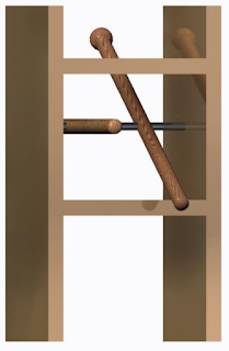
- Set up Arduino IDE
- Used a breadboard to connect the Arduino to a servo. The sweep sample code was uploaded to the Arduino and run.
- Experiments were performed to learn about the servos and the Arduino IDE. A second servo was added to the circuit, and various values were tested in the for loop of the sweep program.
- Blog was set up and published to catalog project.
- Brainstorming and drawing concept sketches was done to begin the project.
Week 2 1/19/17
- Experimented with solenoids.
- Sketched out multiple ideas for drum stick actuation (Figure 1).
- Decided to use servos and zipties for the auxiliary rim and shell sticks. Also decided to use a combination of a spring and solenoid for the main pair of drum sticks.
- Outlined the theory of operation for all four sticks (Figure 2).
- Sketched overall design, including the wooden framework for all of the sticks (Figure 3).
- Worked on bill of materials.
Figure 1
Figure 2
Figure 3
Week 3 1/25/17
- Composed full design report and updated sketch of entire project (Figure 1).
- Solenoid we ordered was a pull solenoid instead of a push/pull solenoid. We need to do more research regarding parts, so we can order them as soon as possible. For now, we will use the parts provided in the labs.
- Several measurements, as indicated in Figure 1, are not known. Using experimental data collected in lab, we will try to determine optimal measurements for these dimensions.
- Wooden construction of the frame has been conceptualized. Logistics of fabrications are not yet known. We will discuss our design with the faculty in the shop during lab period.
Figure 1


Week 4 2/2/17
- Developed CAD renderings of the stick housing frame. This will be the fabricated part for our project (Figure 1,2).
- Revisited solenoid-controlled stick design. Push-pull solenoids will be required. In order to accommodate for this component, holes will have to be drilled in the first layer of the wooden frame.
- Included screws in sketch to show how the frame will be constructed (Figure 3).
Figure 1
Figure 2
Figure 3
Week 5 2/8/17
- Due to the thin 1/4" depth of the wood boards made available to us, we decided to assemble the frame with wood glue instead of screws.
- Additionally, these thin panels required the attachment of thin base beams first. These beams were cut in the dimensions of 1 1/2" x 3/4" x 9".
- In order to prevent the shelf from buckling while it dried, we applied lead weights evenly spread across the surface until it was flat (Figure 1).
- The top shelf will be glued in the same fashion as the bottom shelf.
- In order to secure the drumsticks to the metal rod, we drilled a hole with a drill press with a 1/4" bit (Figure 2, 3).
- The range of motion of these drumsticks was tested in a mock setup without the frame or solenoids (Figure 4).
- More updates are reflected in the notebook sketches in Figure 5. In order to compensate for the bottom pin of the solenoid, a small block will be glued to the bottom shelf with a hole drilled in it that will house the pin as it moves in and out. Additionally, several of the measurements that were previously unknown were calculated and reflected in the updated design sketches. The exact distance between the top and bottom shelves is still not known. Once the main drumsticks are rigged to the frame, this distance can be calculated. It is currently difficult to theoretically determine.
Figure 1

Figure 2

Figure 3
Figure 4
Figure 5
Week 6 2/16/17
- We cut and drilled holes into two small blocks used to contain the solenoids.
- We glued the top shelf on the wooden frame after drilling holes in the sides to push the metal rod into.
- The rod was placed much closer to the front than the earlier design called for in order to allow for flexibility in testing and evaluating multiple positions of the solenoids.
- During our test of the main drumsticks, we did not have access to the solenoid-housing blocks, as they were in the Innovation Studio. Therefore, one of us held the solenoids in place while the other input MIDI commands to the Arduino through a computer (Figure 1).
- While the auxiliary drumsticks were still not attached to the frame, we tested the functionality of the Arduino and Processing code. The code functioned without error (Figure 2).
- The Arduino and the breadboard circuit connecting all of the actuators rests safely on the lower shelf of the wooden frame (Figure 3).
Figure 1
Figure 2
Figure3


No comments:
Post a Comment